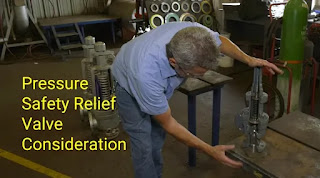
Pressure Safety Relief Valve Consideration, PSV (Pressure Safety Valves) or PRV (Pressure Relief Valve) may never be activated, however they must be d

See Term, Definitions, Acronyms, and Abbreviations on API RP 521 Pressure Relieving and Depressurizing System:

Spring-loaded pressure-relief valve actuated by the static pressure upstream of the valve, which normally opens in proportion to the pressure increase over the set pressure. Normally used with incompressible fluids
Safety Valve:
Spring-loaded pressure-relief valve actuated by the static pressure upstream and characterized by rapid opening or pop action
Safety Relief Valve:
Spring-loaded pressure-relief valve that can be used as either a safety valve or relief valve depending on the application
PSV (Pressure Safety Valves) or PRV (Pressure Relief Valve) may never be activated, however they must be designed and maintained to function correctly on demand. This article provides an introduction to common considerations for PSV selection and operation.
The most commonly used PSV types are; Conventional, Balanced-Bellows and Pilot-Operated. API 520 Part I defines these PSVs as follows:
- Pilot-operated – Pressure-relief valve in which the major relieving device or main valve is combined with and controlled by a self-actuated auxiliary pressure-relief valve (pilot).
- Balanced-bellows – A spring-loaded pressure-relief valve that incorporates a bellows or other means for minimizing the effect of backpressure on the operational characteristics of the valve.
- Conventional – A spring-loaded pressure-relief valve whose operational characteristics are directly affected by changes in the backpressure.
- Set pressure and accumulation
- limits Inlet installation and pressure drop considerations
- Outlet installation and backpressure considerations
- Acoustic Induced Vibration on piping at PSV discharge
- Cold Temperature Metal Embrittlement (CTME) on piping at PSV discharge
- Set Pressure and Accumulation Limits
ASME Section VIII is the industry code that governs the design and fabrication of pressure vessels. The maximum allowable working pressure (MAWP) is the maximum gauge pressure rating stamped on an ASME pressure vessel after it is fabricated. The MAWP is based on the nominal plate thickness used in fabrication; it is always equal to or greater than the desired design pressure. MAWP is typically the basis for the pressure setting of relief devices that protect the vessel.
The maximum allowable accumulated pressure (MAAP) is the pressure increase over the MAWP allowed only during a relieving event. This relieving event is also called an overpressure contingency. ASME Section VIII states the following criteria for MAAP:
The maximum allowable accumulated pressure (MAAP) is the pressure increase over the MAWP allowed only during a relieving event. This relieving event is also called an overpressure contingency. ASME Section VIII states the following criteria for MAAP:
- Greater of 10% of MAWP or 3psi for process contingency with a single relief device protecting
- Greater of 16% of MAWP or 4psi for process contingency with multiple relief device protecting
- 21% of MAWP for external fire exposure contingency
1. Set Pressure
Set Pressure is the pressure at which the pressure-relief device is set to open under service conditions. Overpressure is the pressure increase over the set pressure of the relieving device. Overpressure is the same as accumulated pressure (accumulation) only when the relieving device is set to open at the MAWP of the vessel.2. Inlet Installation and Pressure Drop Considerations
When designing inlet piping to a relief valve, the following should be considered:- Inlet line pressure drop or non-recoverable losses should be limited to 3% of the set pressure for all overpressure contingencies. High inlet pressure drop may result in (i) chattering of the PSV leading to premature failure (ii) reduced relieving capacity leading to higher accumulated pressure. If inlet line losses are greater than 3% , consideration should given to remote sensing pilot operated relief valves. API 520 Part II Section 4 provides more details.
- PSV should be mounted vertically. Gravity acts on (i) the disc and seat while closing, allowing potential issues with re-seating and (ii) the stem causing extra drag and wear.
- Gate valves must be configured such that the stem is in the horizontal position or upside down to prevent the possibility of the gate becoming detached and blocking the relief path.
- If two or more relief devices are on the same line, the common inlet piping internal cross sectional area must be equal to or greater than the combined inlet area of the individual relief devices.
- Proper support piping for stresses.
- Piping should be free-draining to vessel.
- Isolation valves should be full port and locked or carsealed open.
- All pipe and fittings should have a cross-sectional area equal to or greater than that of the relief device inlet.
3. Outlet Installation and Backpressure Considerations
Superimposed backpressure is the pressure at the outlet of the PSV before it opens i.e. pressure in the discharge system coming from other sources. Built-up backpressure is the increase in pressure at the PSV outlet that develops due to flow after the valve opens.Backpressure is the sum of the superimposed and built-up backpressures. High backpressure will tend to produce a closing force on the PSV disc (conventional and balanced-bellows) which may result in a reduction in lift (reduction in flow capacity), variation in opening pressure and instability.
API 520 Part 1 recommends the following:
- Conventional – Built up backpressure should not exceed the allowable overpressure e.g. when the allowable overpressure is 10 %, the built-up backpressure should not exceed 10 % of the set pressure.
- Balanced-bellows – Total backpressure (superimposed plus built-up) does not exceed approximately 50 % of the set pressure. The PSV manufacturer should be consulted for backpressure limitations (mechanical integrity of the bellows) and capacity correction factors (backpressure correction factors). API 520 Part I Section 5.3 provides additional details.
- Pilot-operated – the valve lift is not typically affected by backpressure.
- Maximum fluid velocity should be limited to 75% of sonic speed (General rule of thumb). Higher velocities can generate noise and high vibration resulting in failure of the piping. Refer to Section 4 below for further details.
- The rated (or actual) capacity of relief valve is used to size discharge lateral (piping) from valve to main relief header for all overpressure contingencies.
- Proper support piping for stresses.
- Piping should be as short as possible.
- Piping should be free-draining such that there is no pocketing or have a low drain point when discharging to the flare header.
- For PSVs relieving to atmosphere, the piping should be elevated approximately 3m (10ft) above any structure and weep holes must be present. API 521 Section 7.3.4 provides additional details.
- Isolation valves should be full port and locked or carsealed open.
4. Acoustic Induced Vibration (AIV) on Piping at PSV discharge
Acoustic energy in high capacity gas pressure reducing systems can cause severe piping vibrations. Excess vibration may cause fatigue and premature failure of piping. The maximum recommended sound power levels to prevent AIV may vary based on proprietary information from Design Firms or operating experience. Carucci and Muller(1982) published a paper ”Acoustically induced piping vibration in high capacity pressure reducing systems” which recommends the sound power level design limit based on piping diameter.Piping designers should be consulted and a more detailed analysis be performed to determine what, if anything, should be done to mitigate high vibration concern.
The internal sound power level (PWL) generated by the Pressure Reducing Device (PRD) is calculated as:
 - Virda")
W = mass flow rate through the PRD (kg/s)
ΔP = pressure drop across the PRD (bar)
P1 = PRD upstream pressure (Bara)
T = Upstream temperature (K)
MW = molecular weight
SFF = Sonic Flow Factor. If sonic conditions exist then SFF = 6; otherwise SFF = 0
5. Cold Temperature Metal Embrittlement (CTME) on piping at PSV discharge
Auto-refrigeration (or the J-T effect) of relieving fluids during a relief scenario can potentially cool the outlet of the PSV and its discharge piping to the point where brittle fracture can occur. PSV discharge piping material selection must consider the relief scenario which results in the lowest PSV discharge temperature. Dynamic simulation software can be used to predict the lowest pipe wall temperature in relation to the fluid temperature for the duration of the relief scenario. However in the absence of an elaborate simulation model a quick simulation check can be done by flashing the fluid across a valve, from the upstream relieving condition to the flare header superimposed pressure (or worst case atmospheric pressure). The assumption for this check is that the pipe wall temperature and fluid temperature are in equilibrium.
- [accordion]
- 1. Pressure Safety Valve PSV PRV
-
- 2. API 520-1 2020 Sizing, Selection, Installation of Pressure-relieving Devices
- 3. API 521 2020 Pressure-relieving and Depressuring Systems
- 1. Pressure Safety Valve PSV PRV
- 2. API 520-1 2020 Sizing, Selection, Installation of Pressure-relieving Devices
- 3. API 521 2020 Pressure-relieving and Depressuring Systems